7SEG9 PMOD
Description
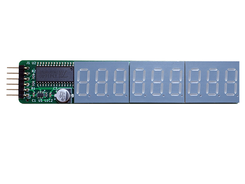
This PMOD provides a 9-digit (3x3) 7-segment LED display output to FPGA designs via a single row PMOD connector. The 7-segment display type is “common cathode”, and it is driven by a TM1640 LED controller IC. The TM1640 IC has its own simplified two-wire serial protocol with similarities to I2C. While the controller IC has power control that eliminates the need for current limiting resistors, it requires 5V power, which is provided by a small DCDC boost converter.
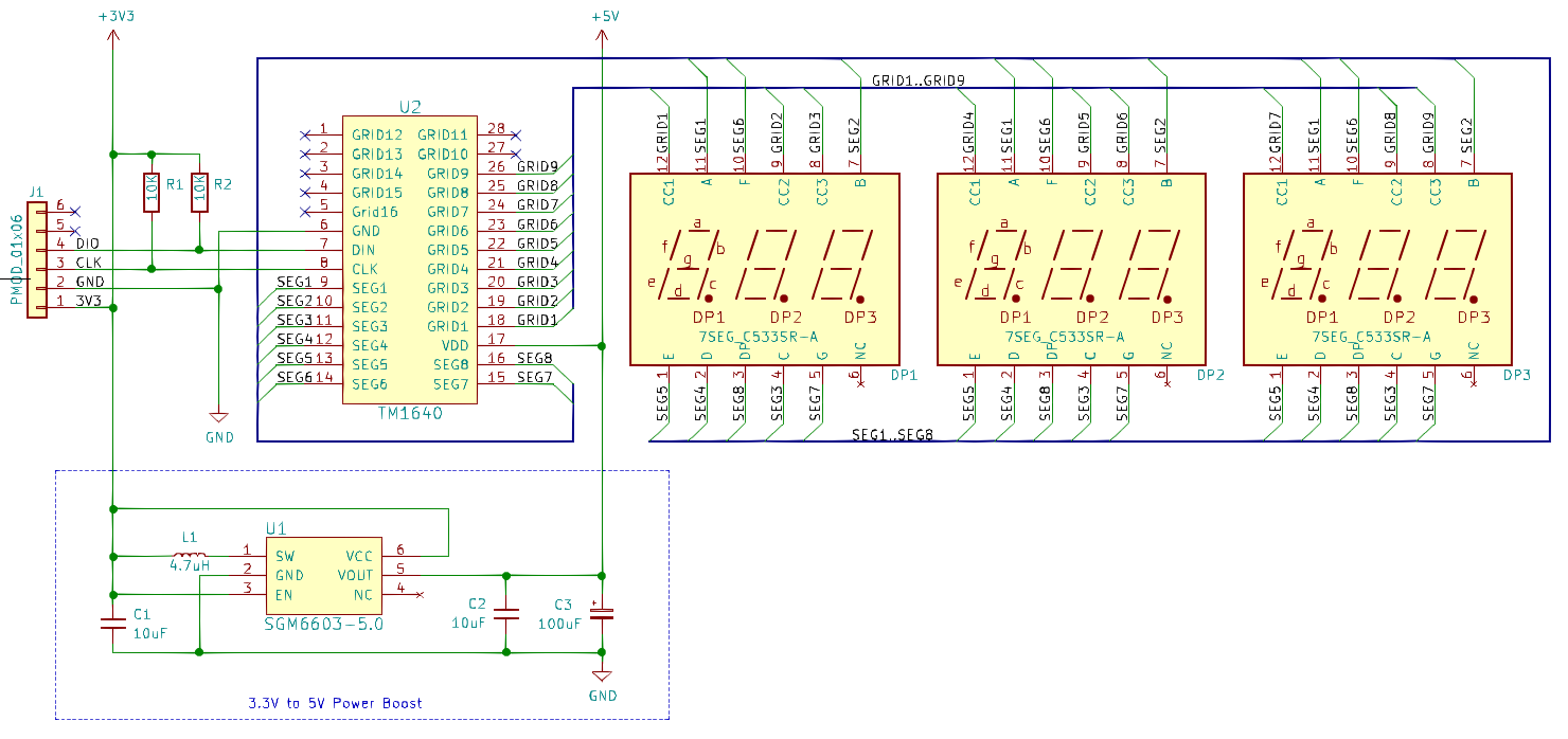
Schematic
PCB Gerber
Pin Assignments
IceBreaker v1.0
| J21 | Label | Description | PMOD1A |
|---|---|---|---|
| 1 | - | Not connected | 4 |
| 2 | - | Not connected | 2 |
| 3 | - | Not connected | 47 |
| 4 | - | Not connected | 45 |
| 7 | - | Not connected | 3 |
| 8 | - | Not connected | 48 |
| 9 | tm_clk | Clock Signal | 46 |
| 10 | tm_din | Data Signal | 44 |
| J22 | Label | Description | PMOD1B |
|---|---|---|---|
| 1 | - | Not connected | 43 |
| 2 | - | Not connected | 38 |
| 3 | - | Not connected | 34 |
| 4 | - | Not connected | 31 |
| 7 | - | Not connected | 42 |
| 8 | - | Not connected | 36 |
| 9 | tm_clk | Clock Signal | 32 |
| 10 | tm_din | Data Signal | 28 |
| J23 | Label | Description | PMOD2 |
|---|---|---|---|
| 1 | - | Not connected | 26 |
| 2 | - | Not connected | 23 |
| 3 | - | Not connected | 20 |
| 4 | - | Not connected | 18 |
| 7 | - | Not connected | 27 |
| 8 | - | Not connected | 25 |
| 9 | tm_clk | Clock Signal | 21 |
| 10 | tm_din | Data Signal | 19 |
DE0-Nano-SoC
The connection to Intels DE0-Nano-SoC is made through the pmod2nano adapter.
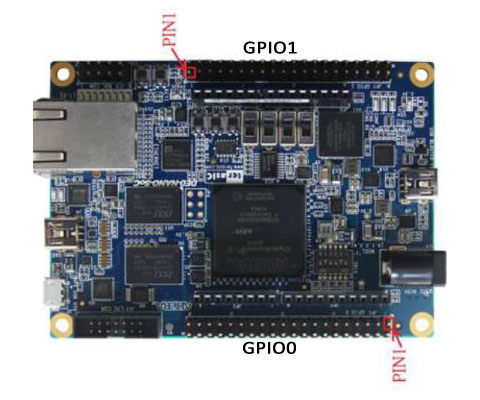
DE0-Nano-SoC is still to bee tested.
Protocol Example
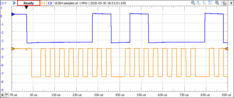
The oscilloscope visualizes the protocol data transmission. Blue = data signal, Orange = clock signal.
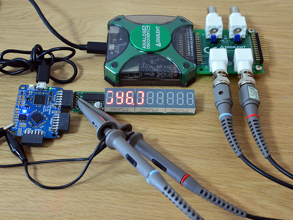
7SEG9 PMOD, connected to a Icebreaker v1.0 board, during protocol analysis
Example Code
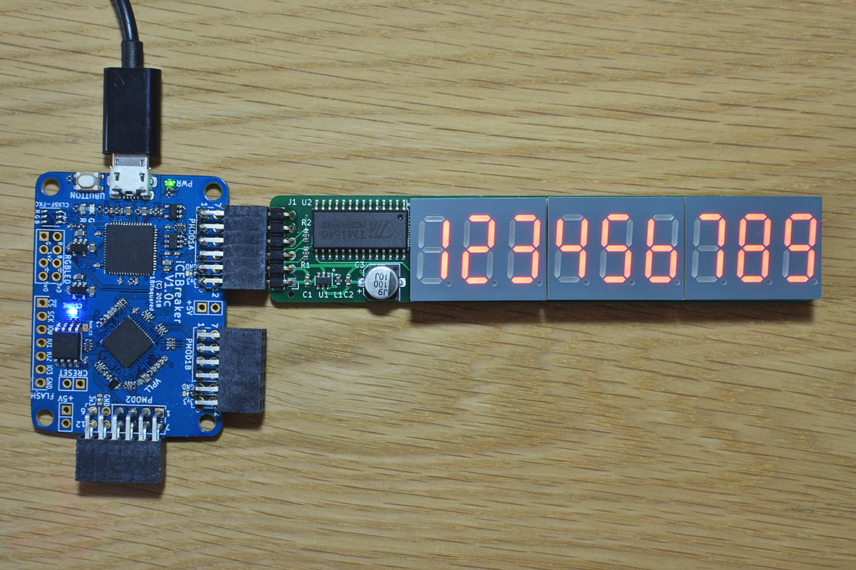
7seg9 PMOD, running test program pmod_7seg4_1.v
Verilog
Verilog test program pmod_7seg4_1.v (top-level):
// -------------------------------------------------------
// This program turns on the display and shows "123456789"
//
// Adopted for TM1640 IC protocol from the TM1637 verilog
// example at https://github.com/alangarf/tm1637-verilog.
// -------------------------------------------------------
module pmod_9seg9_1(
  input clk,
  output tm_clk,
  output tm_din
);

reg rst = 1;
reg [18:0] counter;
reg [7:0] instruction_step;
reg tm_latch;
reg [7:0] tm_byte;
reg tm_end;
reg tm_busy;

tm1640 disp ( clk, rst, tm_latch, tm_byte, tm_end,
              tm_busy, tm_clk, tm_din );

always @(posedge clk) begin
  if (rst) begin   // rst runs only once at start time
    counter <= 0;
    instruction_step <= 0;
    tm_latch <= 0;
    tm_byte <= 0;
    tm_end <= 0;
    rst <= 0;
  end
  else begin       // start sending the list of instructions
    if (tm_busy == 0 && instruction_step < 13) begin
      case (instruction_step)
        1: begin
          // -------------------------------------------------
          // Command1 | 0 | 1 | x | x | N | I | x | x | DATA
          // N = Normal (0), I = Addr incr (0), x = N/A (0)
          // -------------------------------------------------
          tm_byte <= 8'b01000010;
          tm_end <= 1;
          tm_latch <= 1;
        end
        2: begin
          // -------------------------------------------------
          // Command2 | 1 | 1 | x | x | D | C | B | A | ADDR
          // A,B,C,D =  LED adddress in bin (range 0x0..0xF)
          // -------------------------------------------------
          tm_byte <= 8'b11000000;
          tm_end <= 0;
          tm_latch <= 1;
        end
        3: begin
          // -------------------------------------------------
          // Data1, write '1'
          // -------------------------------------------------
          tm_byte <= 8'b00000110;
          tm_end <= 0;
          tm_latch <= 1;
        end
        4: begin
          // -------------------------------------------------
          // Data2, write '2'
          // -------------------------------------------------
          tm_byte <= 8'b01011011;
          tm_end <= 0;
          tm_latch <= 1;
        end
        5: begin
          // -------------------------------------------------
          // Data3, write '3'
          // -------------------------------------------------
          tm_byte <= 8'b01001111;
          tm_end <= 0;
          tm_latch <= 1;
        end
        6: begin
          // -------------------------------------------------
          // Data4, write '4'
          // -------------------------------------------------
          tm_byte <= 8'b01100110;
          tm_end <= 0;
          tm_latch <= 1;
        end
        7: begin
          // -------------------------------------------------
          // Data5, write '5'
          // -------------------------------------------------
          tm_byte <= 8'b01101101;
          tm_end <= 0;
          tm_latch <= 1;
        end
        8: begin
          // -------------------------------------------------
          // Data6, write '6'
          // -------------------------------------------------
          tm_byte <= 8'b01111100;
          tm_end <= 0;
          tm_latch <= 1;
        end
        9: begin
          // -------------------------------------------------
          // Data7, write '7'
          // -------------------------------------------------
          tm_byte <= 8'b00000111;
          tm_end <= 0;
          tm_latch <= 1;
        end
        10: begin
          // -------------------------------------------------
          // Data8, write '8'
          // -------------------------------------------------
          tm_byte <= 8'b01111111;
          tm_end <= 0;
          tm_latch <= 1;
        end
        11: begin
          // -------------------------------------------------
          // Data9, write '9'
          // -------------------------------------------------
          tm_byte <= 8'b01101111;
          tm_end <= 1;
          tm_latch <= 1;
        end
        12: begin
          // -------------------------------------------------
          // Command3 | 1 | 0 | x | x | D | U | M | L | CTRL
          // D = Display on/off, U = upper brightness bit,
          // M = mid brightness bit, L = low brightness bit
          // -------------------------------------------------
          tm_byte <= 8'b10001111;
          tm_end <= 1;
          tm_latch <= 1;
        end
      endcase

      instruction_step <= instruction_step + 1;
    end
    else if (tm_busy == 1) begin
      tm_latch <= 0;
    end
  end
end
endmodule
VHDL
TBD
Linux
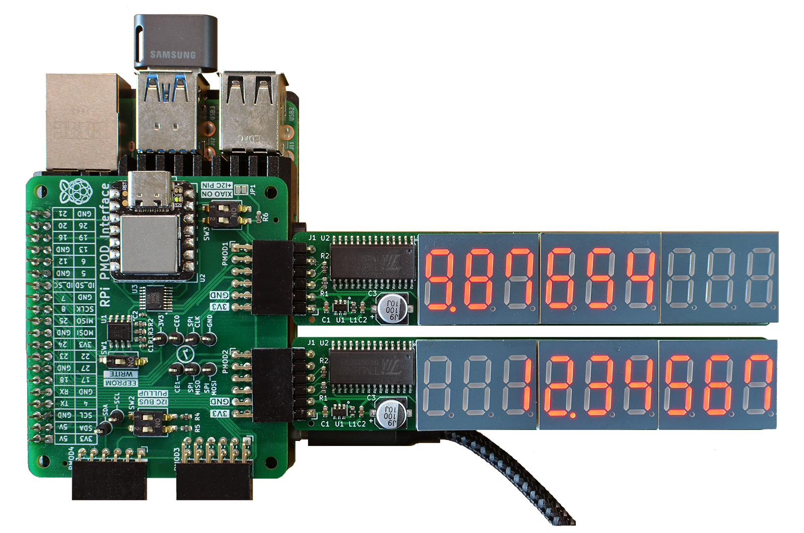
Two 7seg9 PMODs with the TM1640 controller IC, connected to a Raspberry Pi 4 through the PMOD2RPI interface board. Linux 'C' driver code for the 7seg9 PMOD is located in github at
https://github.com/fm4dd/pmod-7seg9/tree/master/examples/pi-tm1640