PMOD2RPI
Description
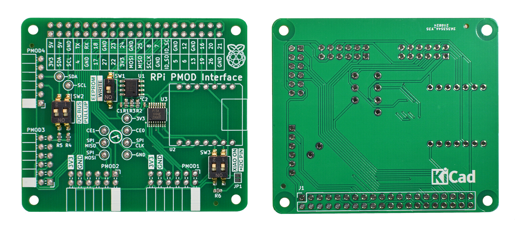
PMOD2RPI is a PMOD-compatible Interface Board for the Raspberry Pi B-type GPIO connector. It provides a total of four PMOD connectors to run PMOD-compatible modules on the Raspberry Pi. This board is compatible to PMOD interface standard v1.3.1 by Digilent Inc. The PMOD (peripheral module interface) standard enables simple plug-in connectivity between FPGA or microcontroller development boards, and a range of input/output modules.
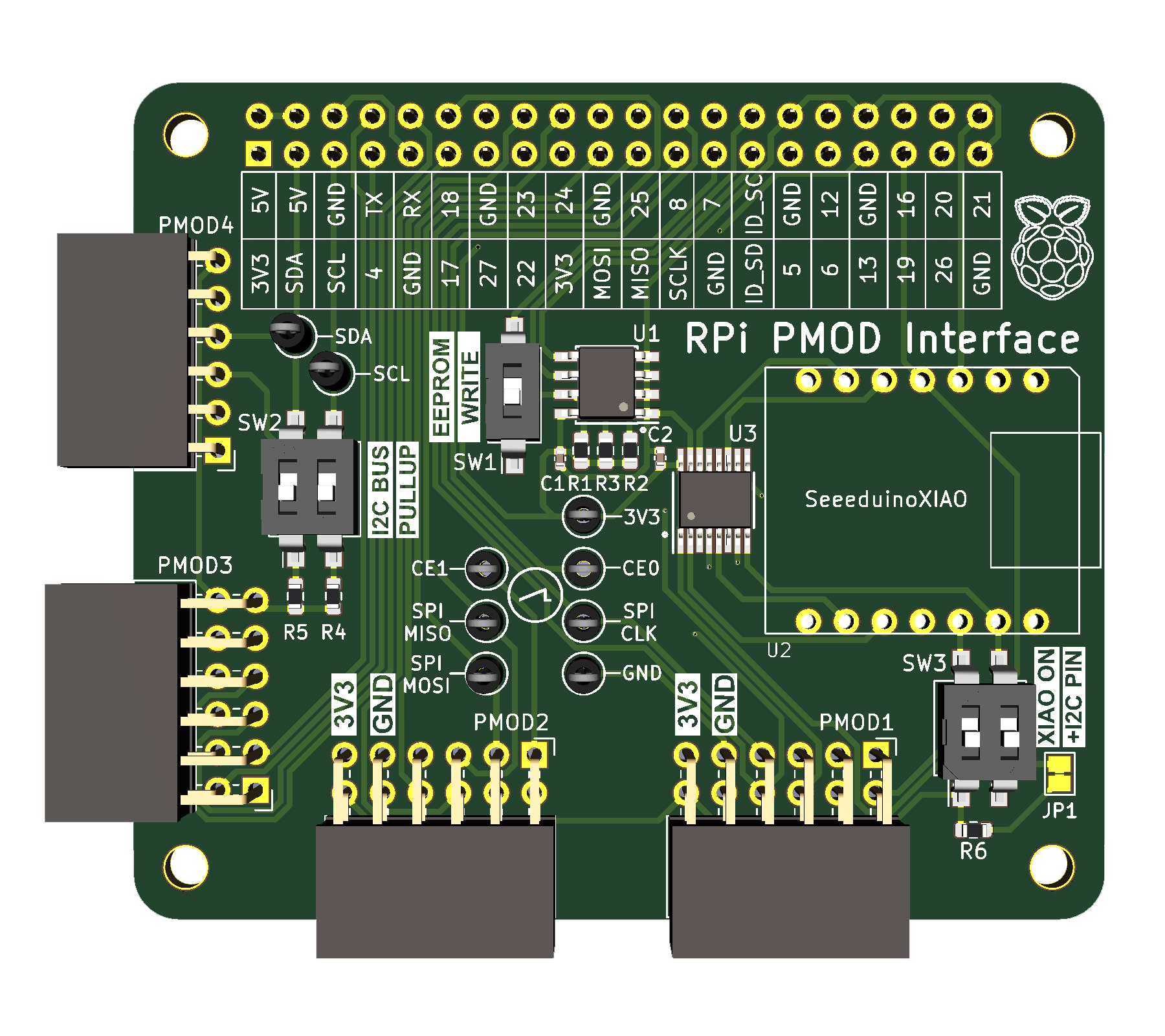
While all connectors provide digital IO, they also double as serial bus connectors for I2C and SPI modules. To aid troubleshooting, a set of Keystone miniature testpins can be fitted to create access for oscilloscope and DMM monitoring. A Seeeduino XIAO footprint has been added to additionally drive two of the four PMOD's, or to communicate with the RPi. The XIAO is optional, and can operate with the board "standalone" if needed.
I2C /SPI signal switching on PMOD1
The PMOD interface standard v1.3.1 added a new extended I2C connector type 6A, which runs the I2C bus signals over the same pins 3/4 that are already used for SPI. In order to allow both bus types to be used on a single connector, switch SW3 allows to swap the I2C signals between pins 3/4 and 9/10 on PMOD1.
See also http://fpga.fm4dd.com/
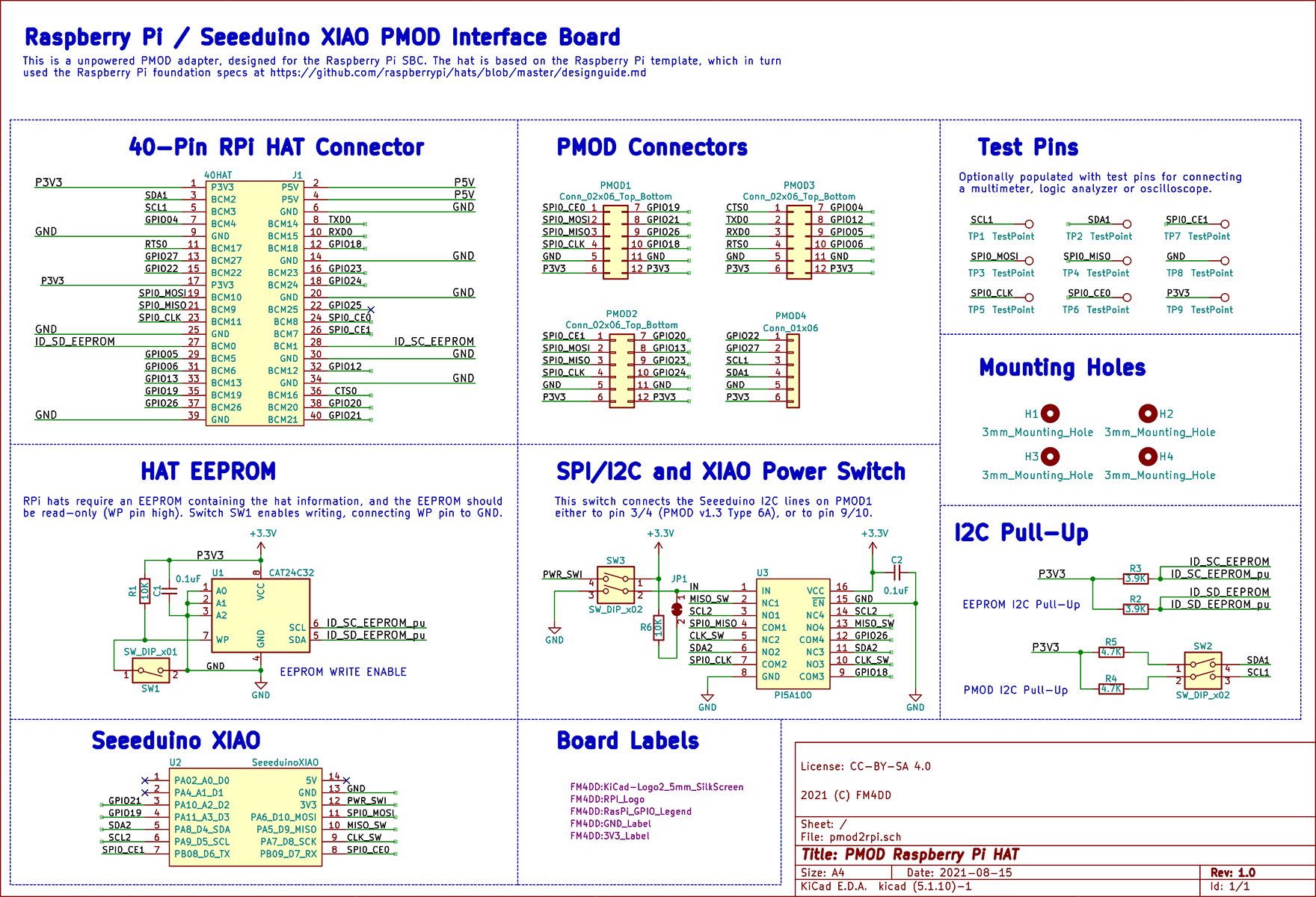
Schematic
Hardware Versions
| Version | Gerber | Schema |
|---|---|---|
| 1.0 | 20210821-pmod2rpi-gerber-v10.zip | 20210821-pmod2rpi-schema-v10.pdf |
Build documentation
Raspberry Pi 40-Pin Connector GPIO assignment list
| RPi Pin-# | RPi Pin Name | PMOD#-Pin# | RPi Pin-# | RPi Pin Name | PMOD#-Pin# |
|---|---|---|---|---|---|
| 1 | 3V3 | All (Pin-6) | 2 | 5V | - |
| 3 | GPIO02 | PMOD4-4 | 4 | 5V | - |
| 5 | GPIO03 | PMOD4-3 | 6 | GND | All (GND Pin-5) |
| 7 | GPIO04 | PMOD3-7 | 8 | GPIO14 | PMOD2-1 |
| 9 | GND | All (GND Pin-5) | 10 | GPIO15 | PMOD3-3 |
| 11 | GPIO17 | PMOD3-4 | 12 | GPIO18 | PMOD1-10 |
| 13 | GPIO27 | PMOD4-2 | 14 | GND | All (GND Pin-5) |
| 15 | GPIO22 | PMOD4-1 | 16 | GPIO23 | PMOD2-9 |
| 17 | 3V3 | All (Pin-6) | 18 | GPIO24 | PMOD2-10 |
| 19 | GPIO10 | PMOD1-2, PMOD2-2 | 20 | GND | All (GND Pin-5) |
| 21 | GPIO09 | PMOD1-3, PMOD2-3 | 22 | GPIO25 | PMOD2-10 |
| 23 | GPIO11 | PMOD1-4, PMOD2-4 | 24 | GPIO08 | PMOD1-1 |
| 25 | GND | All (GND Pin-5) | 26 | GPIO07 | PMOD2-1 |
| 27 | ID_SD_EEPROM | U1 EEPROM SDA | 28 | ID_SC_EEPROM | U1 EEPROM SCL |
| 29 | GPIO05 | PMOD3-9 | 30 | GND | All (GND Pin-5) |
| 31 | GPIO06 | PMOD3-10 | 32 | GPIO12 | PMOD3-8 |
| 33 | GPIO13 | PMOD2-8 | 34 | GND | All (GND Pin-5) |
| 35 | GPIO19 | PMOD1-7 | 36 | GPIO16 | PMOD3-1 |
| 37 | GPIO26 | PMOD1-9 | 38 | GPIO20 | PMOD2-7 |
| 39 | GND | All (GND Pin-5) | 40 | GPIO21 | PMOD1-8 |
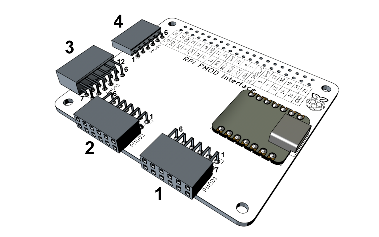
PMOD pinout
PMOD1 pin assignment list
Top Row
| PMOD Pin# | RPi Pin Name | RPi Alternate | RPi Pin-# | XIAO Pin Name | XIAO-Pin# |
|---|---|---|---|---|---|
| 1 | GPIO08 | SPI0_CE0 | 24 | D7 | 8 |
| 2 | GPIO10 | SPI0_MOSI | 19 | D10 | 11 |
| 3 | GPIO09 | SPI0_MISO | 21 | D9 (D5) | 10 |
| 4 | GPIO11 | SPI0_CLK | 23 | D8 (D4) | 9 |
| 5 | GND | GND | 6,9,14... | GND | 13 |
| 6 | 3V3 | - | 1,17 | 3V3 | 12 |
Bottom Row
| PMOD Pin# | RPi Pin Name | RPi Alternate | RPi Pin-# | XIAO Pin Name | XIAO-Pin# |
|---|---|---|---|---|---|
| 7 | GPIO19 | - | 35 | D3 | 4 |
| 8 | GPIO21 | - | 40 | D2 | 3 |
| 9 | GPIO26 | - | 37 | D5 (D9) | 6 (10) |
| 10 | GPIO18 | - | 12 | D4 (D8) | 5 (9) |
| 11 | GND | - | 6,9,14... | GND | 13 |
| 12 | 3V3 | - | 1,17 | 3V3 | 12 |
XIAO pins with alternate pins in () are controlled by the "+I2C Pin" DIP switch setting of SW3.
PMOD2 pin assignment list
Top Row
| PMOD Pin# | RPi Pin Name | RPi Alternate | RPi Pin-# | XIAO Pin Name | XIAO-Pin# |
|---|---|---|---|---|---|
| 1 | GPIO07 | SPI0_CE1 | 26 | D7 | 8 |
| 2 | GPIO10 | SPI0_MOSI | 19 | D10 | 11 |
| 3 | GPIO09 | SPI0_MISO | 21 | D9 (D5) | 10 |
| 4 | GPIO11 | SPI0_CLK | 23 | D8 (D4) | 9 |
| 5 | GND | GND | 6,9,14... | GND | 13 |
| 6 | 3V3 | - | 1,17 | 3V3 | 12 |
XIAO pins with alternate pins in () are controlled by the "+I2C Pin" DIP switch setting of SW3.
Bottom Row
| PMOD Pin# | RPi Pin Name | RPi Alternate | RPi Pin-# |
|---|---|---|---|
| 7 | GPIO20 | - | 38 |
| 8 | GPIO13 | - | 33 |
| 9 | GPIO23 | - | 16 |
| 10 | GPIO24 | - | 18 |
| 11 | GND | - | 6,9,14... |
| 12 | 3V3 | - | 1,17 |
The bottom row is not connected to any XIAO pins.
PMOD3 pin assignment list
Top Row
| PMOD Pin# | RPi Pin Name | RPi Alternate | RPi Pin-# |
|---|---|---|---|
| 1 | GPIO16 | CTS | 36 |
| 2 | GPIO14 | TXD | 8 |
| 3 | GPIO15 | RXD | 10 |
| 4 | GPIO17 | RTS | 11 |
| 5 | GND | GND | 6,9,14... |
| 6 | 3V3 | - | 1,17 |
Bottom Row
| PMOD Pin# | RPi Pin Name | RPi Alternate | RPi Pin-# |
|---|---|---|---|
| 7 | GPIO04 | - | 7 |
| 8 | GPIO12 | - | 32 |
| 9 | GPIO05 | - | 29 |
| 10 | GPIO06 | - | 31 |
| 11 | GND | - | 6,9,14... |
| 12 | 3V3 | - | 1,17 |
The bottom row is not connected to any XIAO pins.
PMOD4 pin assignment list
Pin Row
| PMOD Pin# | RPi Pin Name | RPi Alternate | RPi Pin-# |
|---|---|---|---|
| 1 | GPIO22 | - | 15 |
| 2 | GPIO27 | - | 13 |
| 3 | GPIO03 | I2C_SCL | 5 |
| 4 | GPIO02 | I2C_SDA | 3 |
| 5 | GND | GND | 6,9,14... |
| 6 | 3V3 | - | 1,17 |
Example Code
| Platform | Folder | Description |
|---|---|---|
| Raspberry Pi | pi-tca6424a | I2C module driver 'C' program to control the expander 24 IO output pins individually, and as a set |
| Arduino | xiao-pmod1-i2c24io | Tests I2C ports 0x22 and 0x23. If a module is found, all IO pins are set as 'output=0' (lighting up all LED) |
| Arduino | xiao-pmod1-24iodemo | Creates a lightshow demo by rotating binary patterns over the 24 IO pins, lighting up connected LEDs |
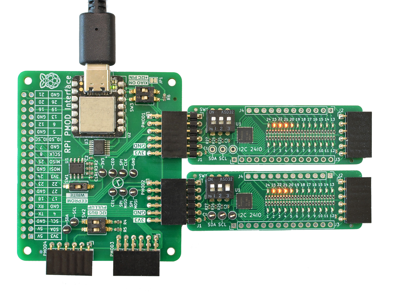
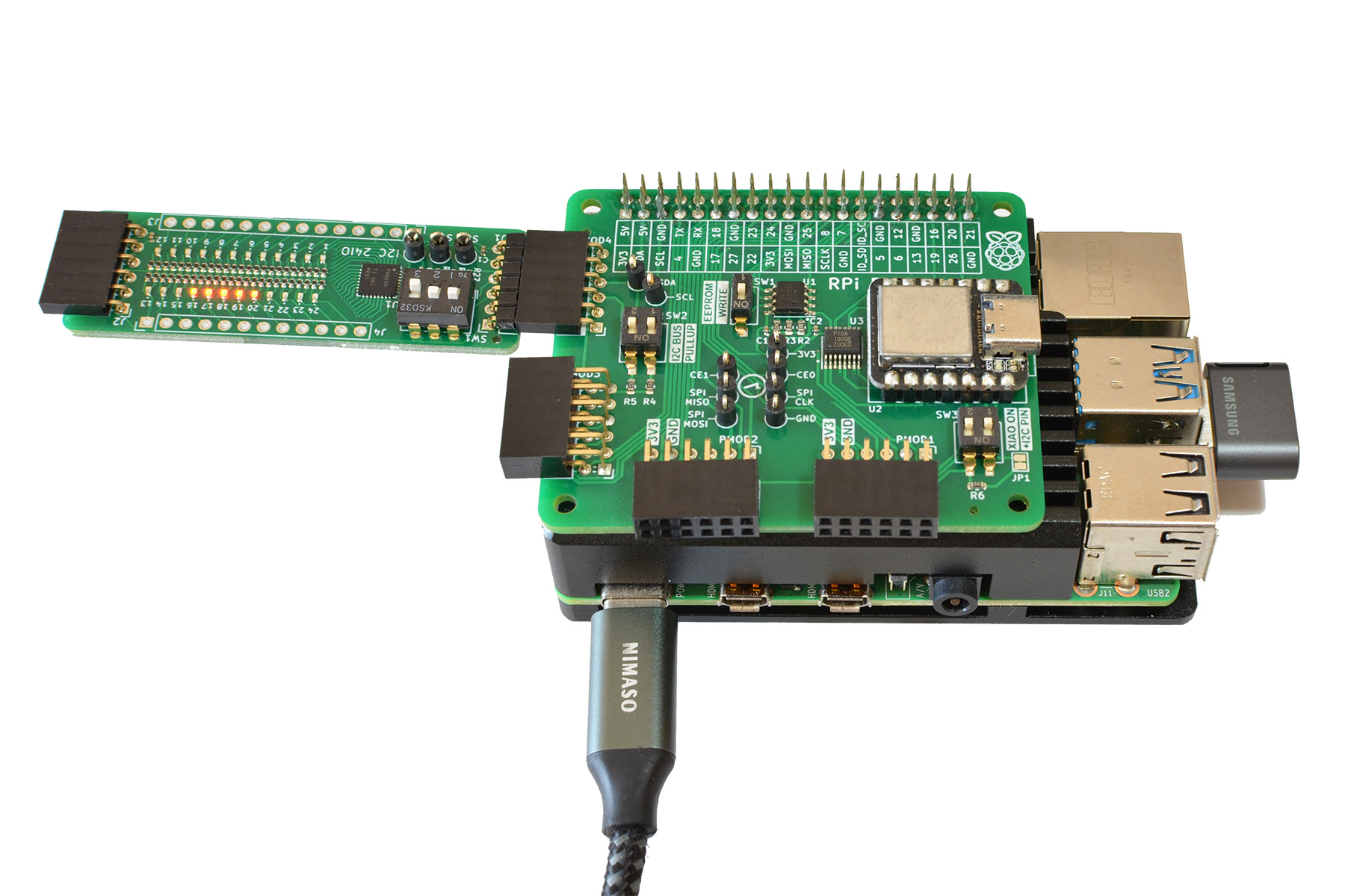
Board Pictures
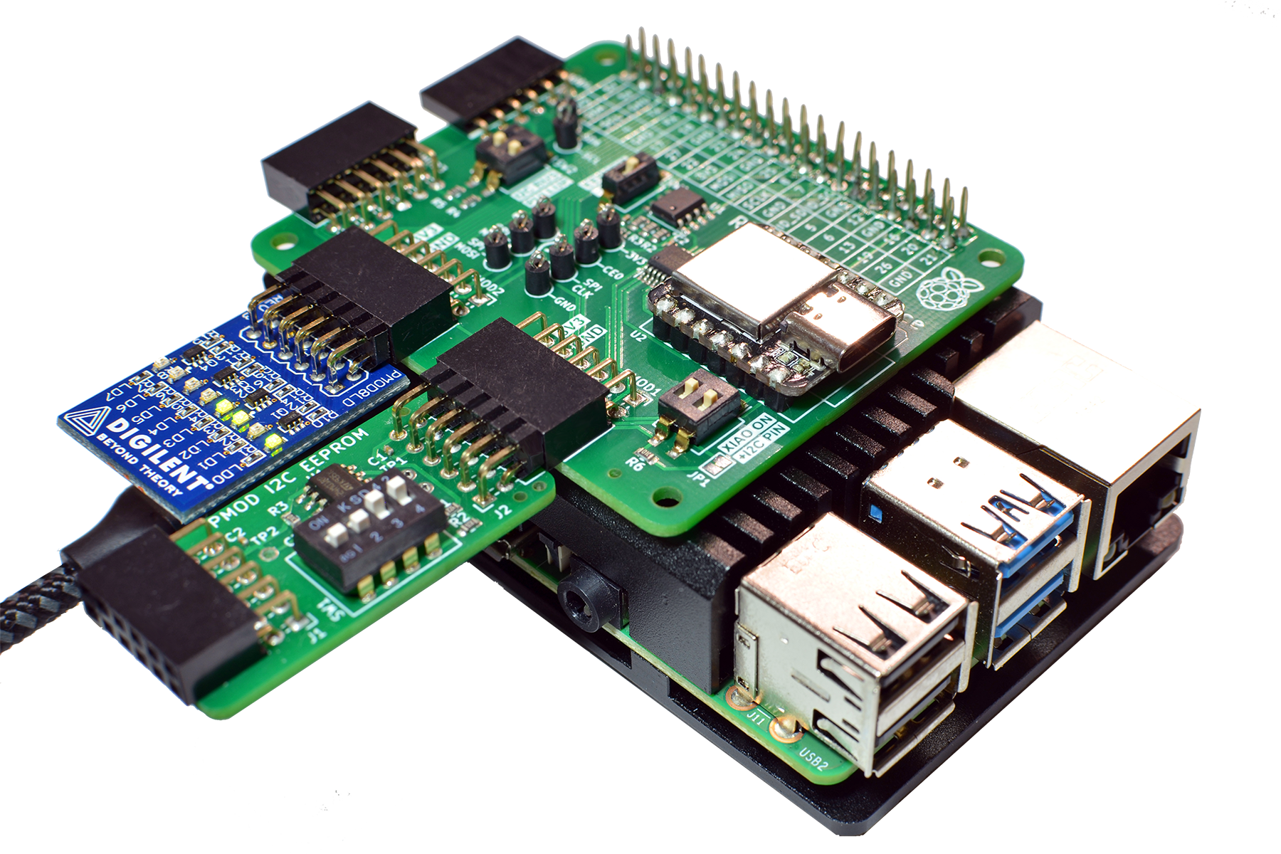
Two I2C24IO PMOD's connected to the RPi PMOD Interface board connector PMOD1 and PMOD2, running the "xiao-double-i2c24io" example program on the Seeeduino XIAO (Cortex M0):
I2C24IO PMOD connected to the RPi PMOD Interface board connector PMOD4, running the "demotca6424a" example program on the Raspberry Pi:
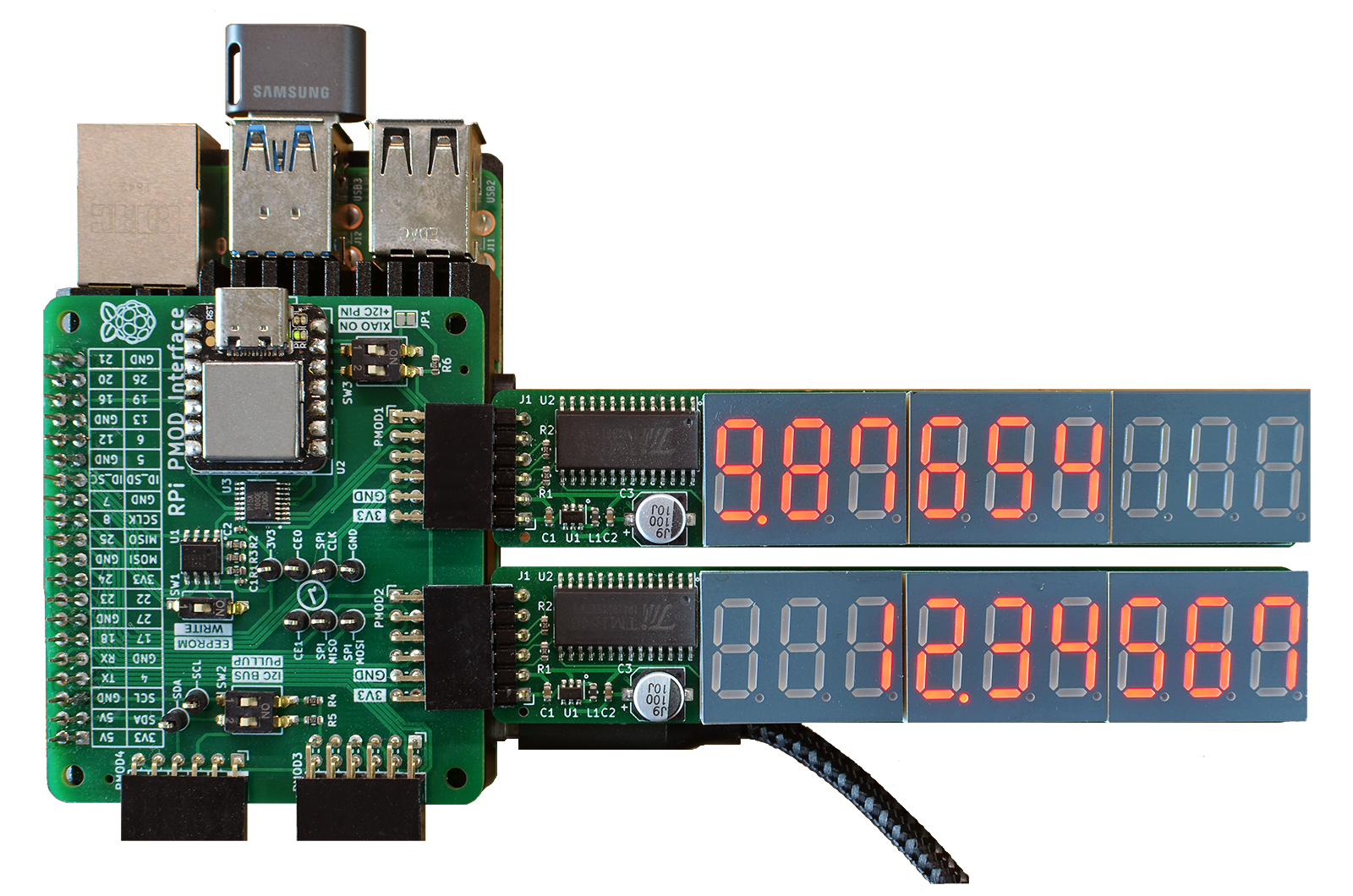
Two 7seg9 PMODs with the TM1640 controller IC, connected to a Raspberry Pi 4 through the PMOD2RPI interface board.